
Post: Airplay sync
Beware of Trolls! This post become technical very fast 😅
Because some of my friends asked me about the mini project I’m currently working here it is. I created a website for it 😎
It short for the last ~3 months I was busy with repurposing old DVD player: Harman-Kardon DVD27.
You might ask me why? Well, I bought myself a set of fancy speakers - and want to connect to them using Apple Airplay 2 - so I can stream from my phone.
Initial idea
-
Repurpose DVD27 somehow to control it’s fancy VFD display.
-
Find a way to control power source of DVD27 - it has standby mode - which is super useful because 99% of the time device will be in standby mode.
-
Reverse engineer VFD controller - PT6315 - and SPI bus in general - in order to display things I want. I had 0 experience in regards to SPI communication in the past - but according to the Wiki it’s quite simple - and most of modern hardware (including Rapsberry PI) - supports SPI.
-
Find a way to decode which button is pressed.
-
Control my old receiver using Compulink.
Heart of the project - Shariport Sync
-
Shariport Sync which can run on Raspberry PI (even on Zero and Zero 2) and provide Airplay service.
-
It can write Metadata of current track in Linux pipe - and I can parse it and do whenever I want with that data.
What was done
- Display current track on VFD screen - I’m using unicode library to convert anything to Latin text (I found it very useful because I listen to a lot of tracks in JPOP with non-latin characters 😊).
- Woke up/put in standby VFD and power source - it has built in power control pin for power source, and uses separate pin for control +3V3 line of front panel.
- Receive metadata from Shariport: events like connection established, disconnect, track name.
What is the goal
- Control everything using single PCB
Revision 1
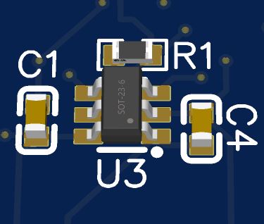
However my first revision of PCB (yes, I made a PCB using EasyEDA) - had incorrectly configured DIR pin 😂 (which is set conversion from 3V3 to 5V).
Incorrectly configured SN74LVC1T45DBVT. Will you be able to notice what’s wrong? 😎
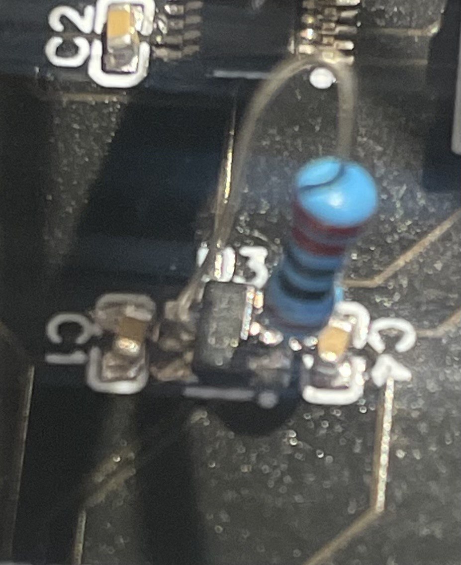
Anyway, I was able to find what’s wrong with this with multimeter - I just added resistor like this (yeah, I have to cut trace a bit with scalpel as well 🤔).
I’ll continue in the next articles 🙂
Comments