
Post: Airplay Sync - control receiver via compulink
Control JVC RX-416V receiver via compulink.
Let’s do quick recap:
- We can control VFD display.
- We know how to turn on power supply, front panel and VFD display.
Let’s focus on controlling receiver. For now on I want only to control the following:
- Power on/off receiver.
- Switch input to
CDif play was requested - because Raspberry PI and HiFi DAC connected via this port.
Reverse engineering compulink protocol
This part is heavily inspired by this repo and a brief history of Compulink.
Quote from the article:
Compulink is a feature present in JVC stereo components in the 80’s (and possibly 90’s). It is a multi-master low speed TTL serial bus that runs over mono 3.5mm cables. The bus lets the stereo components control each other.
Electrical interface
Connection: 3.5mm tip-and-sleeve connector. < . . . > The data is connected to the tip of the 3.5mm connector.
Voltage range: 0-5V, normally low with pull down resistors.
You might already notice some problem: Raspberry PI GPIO pins are 3.3V tolerant. We need to use some kind of level shifter.
While writing this post I realized that I should have used level shifter in my early attempts to implement Compulink. Failure in doing so resulted in burning out MOSI pin on SPI0 😅. (Because I was using this pin as GPIO before ).
I will use Texas Instruments TXB0102DCUT. This IC is a 2-Bit Bidirectional Voltage-Level Translator. Why 2 bit? Because first bit will be used to control front panel standby LED, another bit will be used by Compulink. Please check Page 24 for “Application and Implementation” section for details about the product.
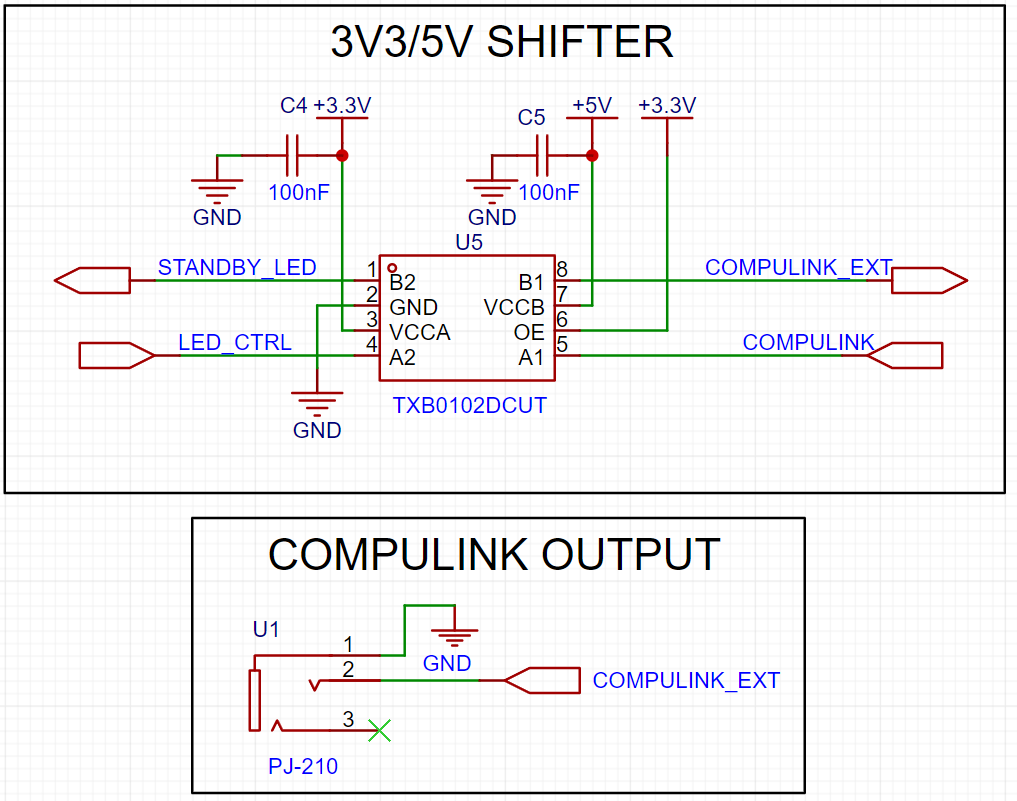
COMPULINKconnects to the any GPIO pin of Raspberry PI (which is 3.3V). In code snippets below, I used GPIO pin 9.COMPULINK_EXTconnects to the 3.5mm female port on PCB. Signal will be converted to 5V voltage domain.
Do we need to control output-enable pin?
The (
OE) input circuit is designed so that it is supplied by VCCA and when the (OE) input is low, all outputs are placed in the high-impedance state. To assure the high-impedance state of the outputs during power up or power down, theOEinput pin must be tied toGNDthrough a pulldown resistor and must not be enabled until VCCA and VCCB are fully ramped and stable.
All of that means we need to control OE pin of the IC from Raspberry PI 😐. One more line to control?!
Then I found this post. We don’t really want to control extra line from Raspberry. Instead, we can connect OE pin to VCCA directly. In this way we will always have output enabled.
Compulink implementation
I wasn’t able to implement compulink using Python - my assumption is that I was not able to control timing of the signal. I decided to use C++ and WiringPi library. Further code samples will be in C++. CMakeLists.txt, and configuration are omitted for brevity.
compulink.h
#pragma once
#ifndef AIRPLAY_COMPULINK_H
#define AIRPLAY_COMPULINK_H

#include <iostream>
#include <wiringPi.h>

#define COMPULINK_PORT 13 // GPIO pin 9
#define POWER_ON 0xC0
#define USE_CD 0xA3

void wordEnd();
void writeHigh();
void writeLow();
void sendCommand(unsigned char hexCode);

#endif
compulink.cpp
// inspired by https://github.com/jcj83429/jvc_compulink
// and http://www.johnwillis.com/2018/09/av-compu-link-unmodulated-ir-daisy.html

#include "compulink.h"

// wordEnd sends a word end signal to the compulink device
// accoring to the compulink spec,
// A word end is encoded as 5ms of 5V to allow the device to latch the data.
void wordEnd()
{
 std::cout << "END\n";
 digitalWrite(COMPULINK_PORT, HIGH);
 delay(5);
 digitalWrite(COMPULINK_PORT, LOW);
}

// writeHigh sends logical high to the compulink device
// accoring to the compulink spec,
// A "1" bit is encoded as 5ms of 5V followed by 15ms of 0V.
void writeHigh()
{
 std::cout << "1";
 digitalWrite(COMPULINK_PORT, HIGH);
 delay(5);
 digitalWrite(COMPULINK_PORT, LOW);
 delay(15);
}

// writeLow sends logical high to the compulink device
// accoring to the compulink spec,
// A "0" bit is encoded as 5ms of 5V followed by 5ms of 0V.
void writeLow()
{
 std::cout << "0";
 digitalWrite(COMPULINK_PORT, HIGH);
 delay(5);
 digitalWrite(COMPULINK_PORT, LOW);
 delay(5);
}

// sendCommand sends a command to the compulink device in MSB format
void sendCommand(unsigned char hexCode) {
 std::printf("0x%x\n", hexCode);
 for (int bitPosition = 7; bitPosition >= 0; bitPosition--)
 {
  int bitValue = (hexCode >> bitPosition) & 1;

  if (bitValue == 0)
  {
   writeLow();
  }
  else
  {
   writeHigh();
  }
 }
 wordEnd();
}
main.cpp
#include "compulink.h"

int main()
{
 if(wiringPiSetup() == -1) {
  std::cerr << "Error initializing WiringPi." << std::endl;
  return 1;
 }

 pinMode(COMPULINK_PORT, OUTPUT);
 // default state of port is HIGH
 digitalWrite(COMPULINK_PORT, LOW);

 for (;;)
 {
  sendCommand(USE_CD);

  delay(1000);
 }
}
Testing
Code above sends USE_CD command every second.
USE_CD is 0xA3 or 10100011 in binary.
I used my oscilloscope to check the signal. Here is the screenshot, with annotated 0 and 1:
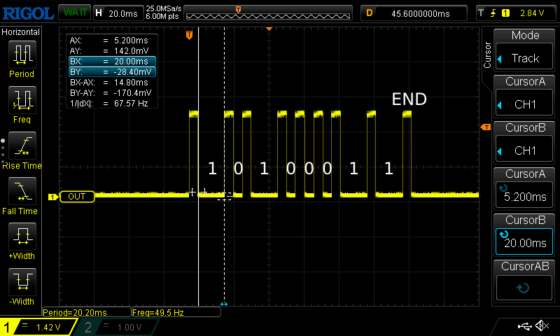
I connected Raspberry PI to the receiver and it works 🎉! Receiver is turned on and input is switched to CD port.
Further testing will be done when I will have my PCB ready 😊
Comments