
Post: Airplay Sync - Standby LED
While my next PCB revision is in production I want to share some of improvements which will go to the new revision.
I want to have some kind of visual feedback that my device is powered on. I will use front panel standby LED for this purpose.
The problem with front panel standby LED
Let’s have a look on front panel schematic (Page 107 of DVD 27 service manual):
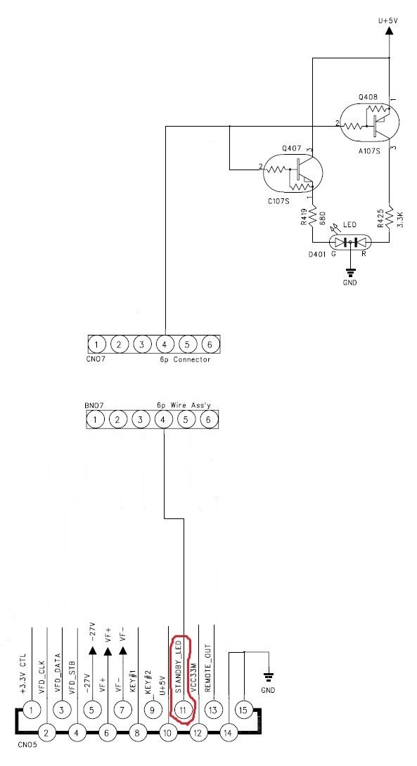
Front panel connector schematic, non relevant parts are omitted.
Note how STANDBY_LED is controlling the LED: it’s connected to bases of both transistors via the same pin! These transistors then controls mixed Green/Red LED. I had hard time to understand how it works.
Simulation of front panel standby LED
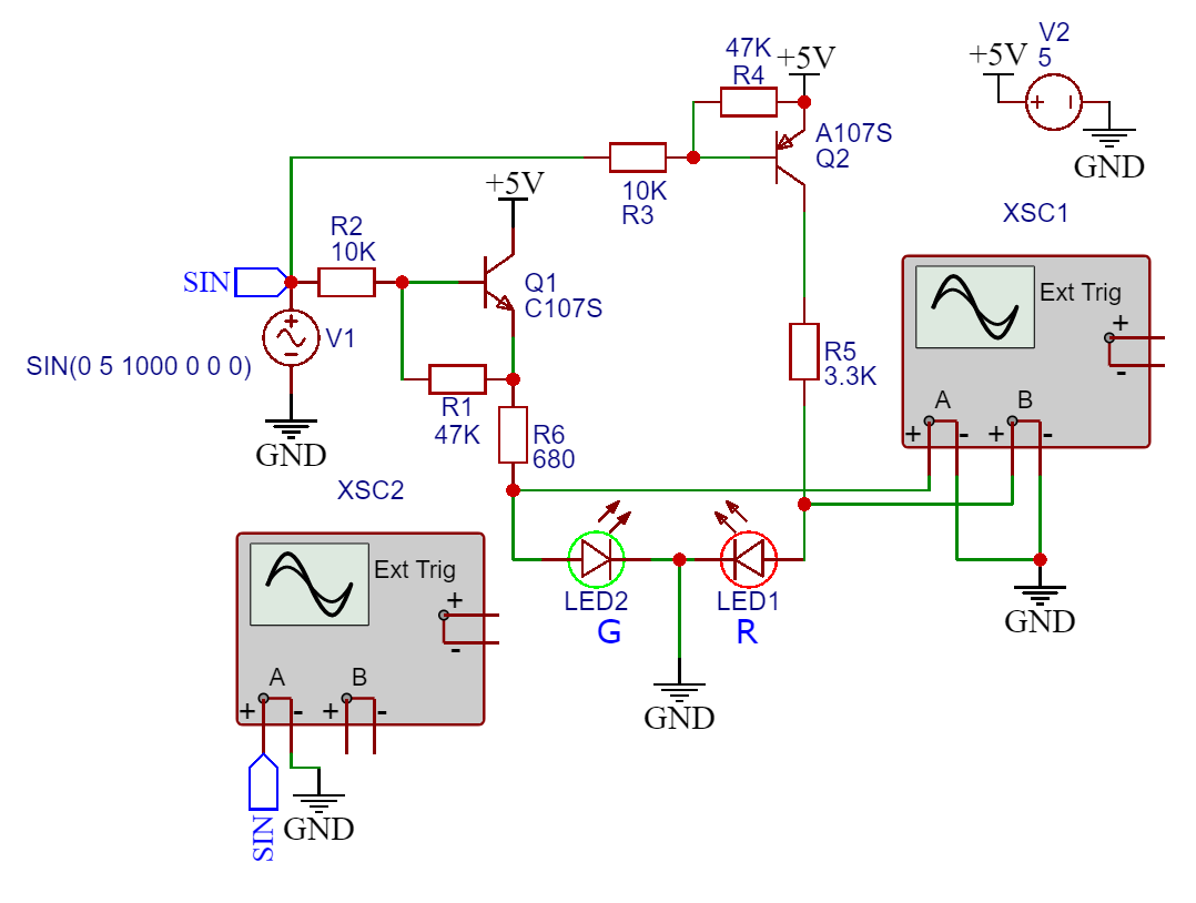
Let’s create “good enough” SPICE models for these transistors. All information is based on these 2 datasheets: C107S and A107S.
* A107S NPN Transistor
* Parameters from the datasheet

.model A107S NPN(IS=150n BF=200 VAF=200 IKF=0.3
+ XTB=1.5 BR=3.0 CJC=8.00E-13 CJE=25.0E-12
+ RB=10 RC=0.1 RE=0.1 VCE=5.0 VBE=0.7
+ Tr=0.07u Tf=0.35u ITF=1.00 VTF=10.0)
* C107S PNP Transistor
* Parameters from the datasheet

.model C107S PNP(IS=150n BF=200 VAF=200 IKF=0.3
+ XTB=1.5 BR=3.0 CJC=8.00E-13 CJE=25.0E-12
+ RB=10 RC=0.1 RE=0.1 VCE=5.0 VBE=-0.7
+ Tr=0.05u Tf=0.36u ITF=1.00 VTF=10.0)
Here is a schematic for simulation:
Simulated oscilloscope screenshot of input on LED1/LED2. Input waveform generated with parameters: Amplitude 5V, 1KHz.
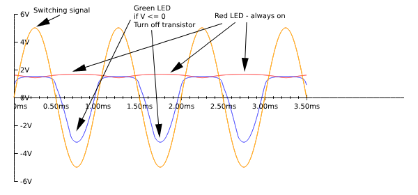
During my physical test - I observed if I supply 5V to STANDBY_LED pin - LED is lit with blue. Without any voltage - LED is red. (I don’t know how they make it blue from mixing red and green).
Simulation confirms this behavior 🎉:
- On positive half cycle of the waveform:
Q1will turn on Green.Q2will turn on Red.- Mix of colors will produce blue.
- On negative half cycle of the waveform:
Q1will turn off Green.Q2will continue to lit.- Only red will be lit so we will see red color.
I still don’t understand however why do they need 2 transistors for this purpose. I think it’s possible to use only one transistor. Maybe they want to have specific brightness of the LED?
Front panel standby LED control
Now we know how to control front panel standby LED. We need to supply 5V to STANDBY_LED pin to lit the LED. We can use this pin to control LED from Raspberry PI.
Raspberry PI GPIO pins are:
-
ON by default! We need to use some kind of inverter to control LED from Raspberry PI. Default state of the LED must be off while Raspberry is booting up. Otherwise we will see LED lit during boot. Later when software starts - LED will be turned off.
-
3.3V tolerant. We need to use some kind of level shifter to control LED from Raspberry PI.
Here is a simple schematic for inverter:
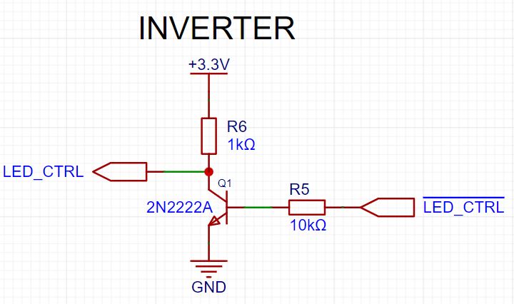
Inverter on 2N2222A transistor.
While testing on breadboard I used 2N2222A transistor. All works as expected:
- LED is off during boot (because Raspberry has 3.3V on the GPIO pin).
- When application is loaded - GPIO pin set to
LOWand LED is lit blue. - If I need I can set GPIO pin to
HIGHand LED will be turned off.
On real PCB I will use SN74LVC1G14DBVR inverter.
Comments