
Post: VFD controller and wiring
My journey started with analyzing original wiring of DVD 27.
I was particularly interested in:
- What VFD controller is on board?
- Which protocol is used to communicate with it?
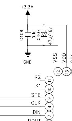
- How to power up controller?
- How was the VFD receiving negative power supply?
Reverse engineering
Page 107 of service manual turns out to be a good source of information (my sincere gratitude towards Harman/Kardon engineers designing this - schematic is clear and well structured).
Let’s go one by one over questions: According to the schematic PT6315 VFD driver is used to control VFD.
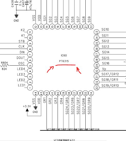
Next question was how to communicate with controller. You probably can already tell based on the pins: 9/STB, 8/CLK, and 7/DIN. But I didn’t know that at the time.
Page 1 of PT6315 datasheet describes capabilities, which are (some omitted):
• Serial Interface for Clock, Data Input, Data Output, Strobe Pins
I have to google it tbh - because, by some reason, “Serial Interface” in my head was related to RS232 interface.
Anyway, at some point I found that Serial Interface actually mean Serial Peripheral Interface.
Wiring VFD controller with Raspberry PI Zero W
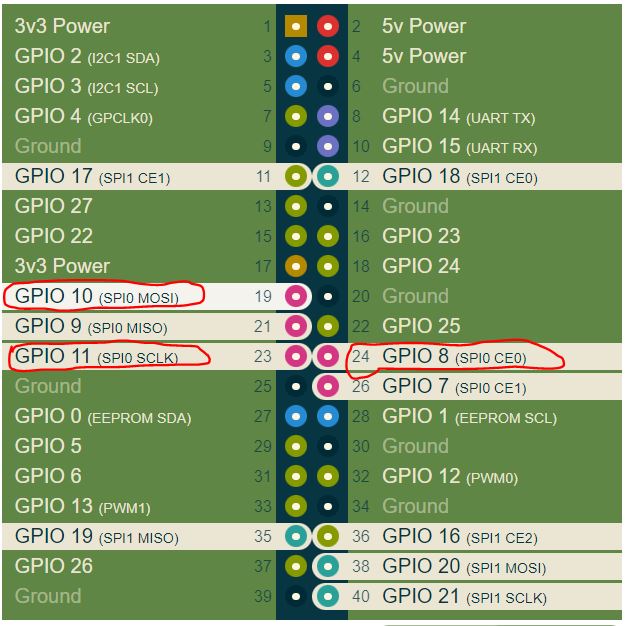
ALl recent Raspberry PIs supports GPIO. I found website which groups pins based on their functions - here.
By default the Pi allows you to use SPI0 with chip select pins on CE0 on GPIO 8 and CE1 on GPIO 7.
GPIO pins I need to use are:
- 10 - MOSI - send data to VFD controller
- 11 - SCLK - clock
- 8 - CE0 - Chip Enable
Here they are on screenshot:
Here my first problem occurs, how to correlate CE(Chip Enable) pins with PT6315?
Turns out SPI is not a standard: is de facto standard. Which means naming can drift.
Soooo, how do I wire it to the front panel anyway? And where to connect it?
Thought process
Lets analyze page 107. Remember we need to find only how to control VFD controller for now.
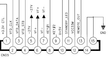
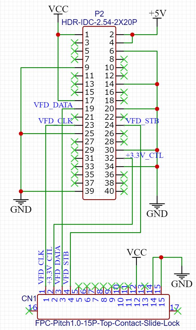
Front port:
VFD controller: SPI and VDD pins:
As you can see SPI port represented by the following pins on the front connector: 2/VFD_CLK, 3/VFD_DATA, 4/VFD_STB.
However I notice something strange in regards to power: VFD driver isn’t connected directly to +3.3V power line, but instead it’s connected via this:
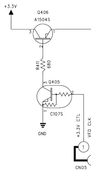
That mean I need to trigger pin 1/+3.3V CTL with +3.3V 🙃 to enable front panel power supply.
Here is schematic for breadboard:
I’ll continue in the next posts how code looks like and how I found that SPI0 port was actually dead on my Raspberry PI 😂 And how to connect negative power pins from Power supply to front panel.
Comments