
Post: VFD controller and Raspberry PI - debugging
Let’s do quick recap of what we know now:
- PT6315 is used to control the VFD display.
- SPI is used to communicate with controller.
- To power up controller, we need to supply +3V3 on pin 1 of the Front panel connector.
- We still doesn’t know however how to provide power supply to VFD display itself.
- We don’t know how to wake up power source.
Breadboard testing with Raspberry PI and VFD
Let’s continue our reverse engineering with tracing back required power rails for VFD display.
Schematic of power supply can be found on page 109 of DVD 27 service manual.
If we check connector on the far right part of the schematic we can find the following connector:
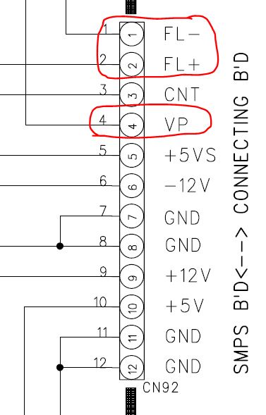
Additionally, pin description on the page 110, describes how main pcb connecting to front panel, and to power source.
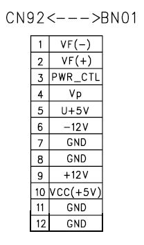
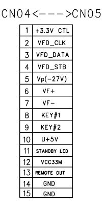
Then our connection should be like this:
- 1/FL- - from power supply to 7/VF- pin of front connector.
- 2/FL+ - from power supply to 6/VF+ pin of front connector.
- 4/VP - from power supply to 5/Vp pin of front connector.
Here is updated breadboard wiring:
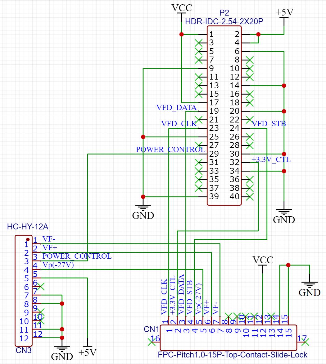
You may notice what I added another connection: 3/CNT - 29/Raspberry PI (line is named POWER_CONTROL).
This pin used to wake up power supply from standby mode. Without +3.3V on this pin VF-/VF+/Vp(-27V) pins are not active.
Preparation for testing of VFD display
In order to test our setup we need to understand what would be the sequence of startup required by VFD controller.
Let’s check docs! VFD controller docs on page 17 describes recommended software flowchart:
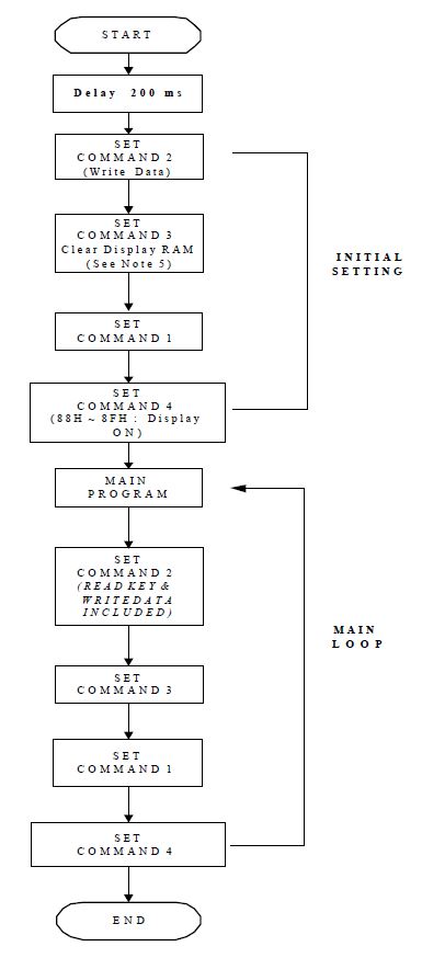
Sooo, there are questions:
- How exactly commands are send?
- What is the command?
Prepare power supply and front panel power
Page 6 describes commands like this:
Commands determine the display mode and status of PT6315. A command is the first byte (b0 to b7) inputted to PT6315 via the DIN Pin after STB Pin has changed from “HIGH” to “LOW” State.
Because at this stage we don’t know much about commands, default mode seems legit for us:
When Power is turned “ON”, the 12-digit , 16-segment modes is selected.
However, from DVD 27 manual on page 86 we can see that VFD display actually has 10 digits, and only suitable configuration for VFD controller would be 10 digits, 18 segments. Let’s hold on for this knowledge for now.
We don’t know however how letters are encoded, but on the page 8 there is test mode for display! Exactly what we need for testing!
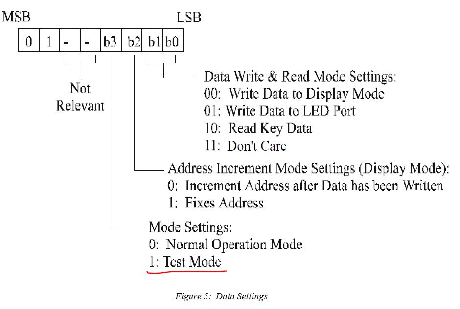
Then the command for the test mode would be like this:
01001000 - where (starting from Most Significant Byte - MSB to Least Significant Byte - LSB):
01- type of command.00- “not relevant”.1- test mode.0- we don’t care about addresses for testing, so why not put “Increment address after data has been written”.00- Write data to display mode, as we want only to display data.
Before we can use Python sketch to send SPI commands, we need to:
- Turn on front panel power supply - by setting
HIGHon GPIO 12 (pin 32). - Switch power source from standby mode - by setting
HIGHon GPIO 5 (pin 29).
Go to your Raspberry PI via SSH and execute the following:
# gpio command line uses GPIO pin numbering
gpio -g mode 12 out
gpio -g mode 5 out

gpio -g write 12 1
gpio -g write 5 1
So now we have power supply switched from standby mode, and front panel receiving +3.3V power supply. We are ready to send some commands!
Test mode of VFD controller
Here is a Python sketch which will send command to VFD controller:
Watch out! This is incomplete code, read further to understand why.
import spidev

bus=0
device=0

spi = spidev.SpiDev()
spi.open(bus, device)
spi.max_speed_hz = 500000
spi.mode = 0b00

#0b prefix used here to tell python to use binary notation
to_send = [0b01001011]
spi.xfer(to_send)
Where did I took max_speed_hz and mode parameters? That’s a bit tricky:
max_speed_hz- Page 19 of PT6315 - Table with electrical characteristics - RowOscillation Frequency- Typical: 500 KHz or 500000 Hzmode- Page 5 - Data Input Pin: This pin inputs serial data at the rising edge of the shift clock (starting from the lower bit). This is equal tomode 0from SPI Wiki page - Mode numbers table.
However, after executing the code above, the VFD display shows nothing. Why?
 Decoded SPI protocol from my oscilloscope, MSB decoder enabled
Well, the hint is above in the mode section:
< . . . > This pin inputs serial data at the rising edge of the shift clock (starting from the lower bit)
While we sent data in MSB mode, VFD controller expects them in LSB mode!
Let’s write new function which will convert MSB word to LSB.
import spidev

# invert binary
def msb_to_lsb(msb_value):
    return int(bin(msb_value)[2:].zfill(8)[::-1], 2)

bus=0
device=0

spi = spidev.SpiDev()
spi.open(bus, device)
spi.max_speed_hz = 500000
spi.mode = 0b00

# 0b prefix used here to tell python to use binary notation

# command 1 - 10 digits 18 segments
spi.xfer([msb_to_lsb(0b00000110)])

# command 2 - test mode
spi.xfer([msb_to_lsb(0b01001011)])

# command 4 turn on display, first indicator will display something
# other segments might turn on as well as we did not clear controller
# ram as suggested in the documentation
spi.xfer([msb_to_lsb(0b10001111)])

# command 4 turn off segment
# spi.xfer([msb_to_lsb(0b10000111)])
Our sketch just displayed test data on VFD display 🎉!
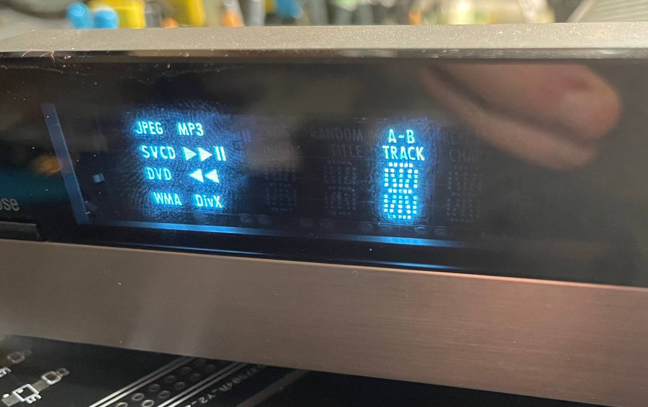 Segment
 A-B/Track and several other was turned on by Python sketch.
 Decoded SPI protocol from my oscilloscope, LSB decoder enabled
Let’s continue in further posts, and actually display something meaningful on the display.
Comments